MODEL 190ABE
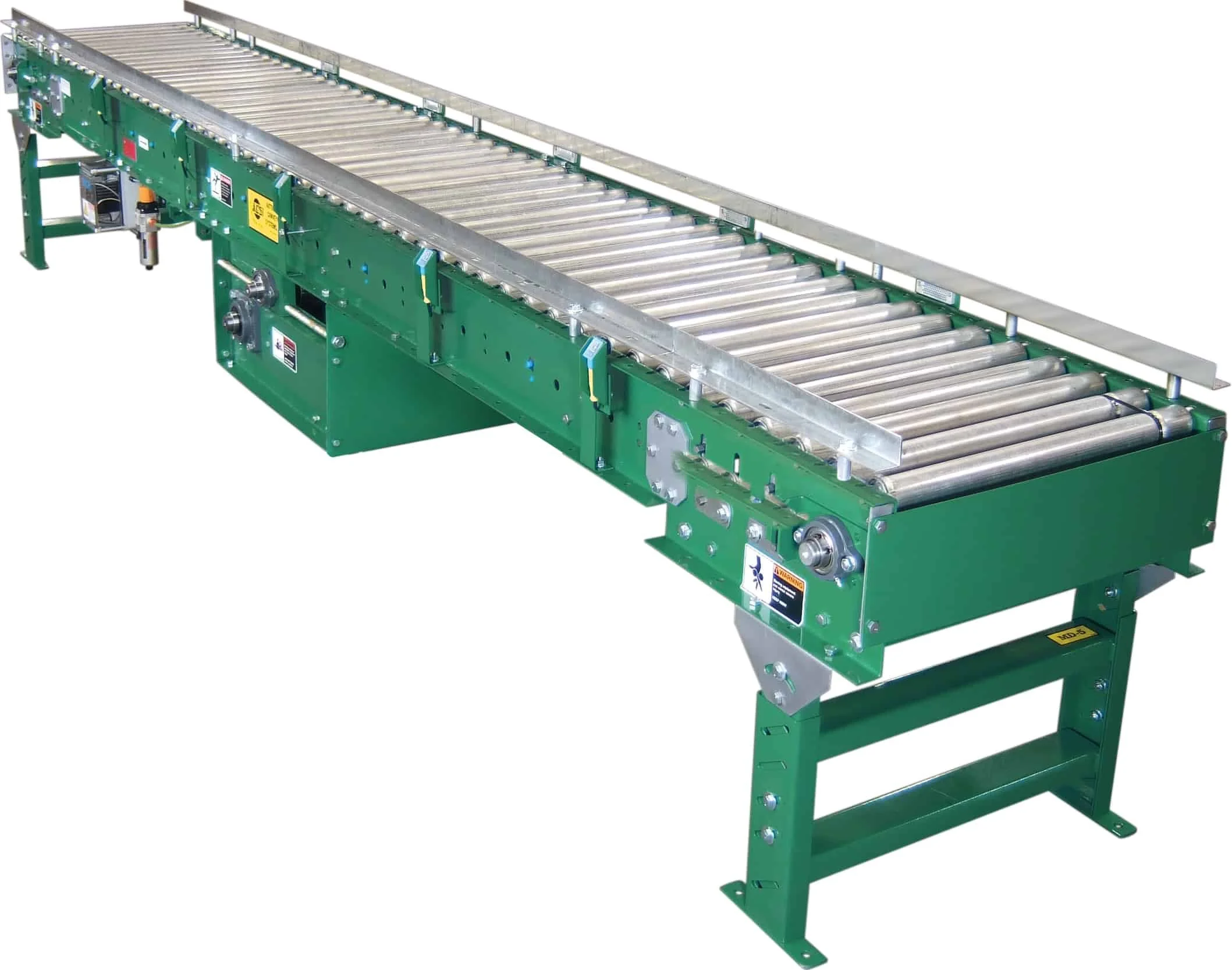
MEDIUM DUTY ZERO PRESSURE PHOTO EYE CONTROLLED ACCUMULATING CONVEYOR
Applications / Features:
Zero Pressure Accumulation
Air Operated Zones
Easy Installation
Economical
No Mechanical Sensor Rollers
Photo Eye Controlled
-
Driving Belt – Black PVC 120 belt.
Bed – Roller bed width between frames, 15″, 21″, 27″, 33″, and 39″. 7″ x 1-1/2″ x 12 gauge powder painted formed steel channel frame, bolted together with butt couplings and floor supports. Frame sections are 10′ 0″ and 5′ 0″ long.
Tread Rollers – 1.9″ diameter x 16 gauge galvanized steel rollers spaced on 3″ or 6″ centers. Safety pop-out design prevents damage to product or harm to personnel if caught between belt and tread rollers.
Pressure Rollers – 1.9″ diameter x 16 gauge galvanized steel rollers with 7/16″ hex shaft spaced on 6″ and 12″ centers. Raised by air to drive tread rollers, lowered when sensing device is activated.
Sensing Device – NEMA 1 photoelectric sensor in each zone detects presence of product and activates accumulation feature in the trailing zone if upstream zone is occupied.
Power Supply – 120 VAC power supply controls accumulation feature with 24 VDC output. Power supply will control 50 accumulation zones.
Air Requirements – Operating pressure is 20-35 psi on main trunk line.
Accumulation Zones – 24″, 30″, or 36″ long, air operated. Conveyor frame lengths change with zone lengths. NOTE: Zone length must be evenly divisible by roller centers.
Filter/Regulator – Supplied loose for mounting to conveyor side frame, with 3/8″ NPT ports. 35 to 40 psi recommended operating pressure with free air consumption of .0062 cu. ft. per sensor operation.
Guard Rails – 1-1/2″ x 1-1/2″ x 12 gauge galvanized angle guard rails, both sides.
NOTE: Product contact with guard rails will affect product flow.
Tail Pulley – 4″ diameter crowned with 1-3/16″ shaft.
Drive Pulley – 8″ diameter crowned and fully lagged with 1-7/16″ diameter shaft. Located at infeed end of conveyor.
Snub Roller – 2-1/2″ diameter adjustable, located directly behind drive pulley. 2″ diameter at each end directly behind terminal pulleys
Return Idlers – 1.9″ diameter adjustable on 10’0″ centers.
Floor Supports – 31-1/2″ to 45-1/2″ adjustable from floor to top of rollers. One support supplied at each end of conveyor and at each bed joint.
Take-Up – Screw type take-up located at end of conveyor to maintain belt tension. 12″ of belt take-up provided.
Bearings – Sealed and prelubricated with cast iron housings.
Speed Reducer – C-Face mounted heavy duty worm gear reducer.
Motor – 1/2 HP 230/460-3-60 TE motor.
Conveyor Speed – 60 FPM constant. Some higher and lower speeds available. However, most efficient accumulation occurs at 60 FPM.
Capacity – 150 pounds per foot max. unit load.
-
Center Drive – Mounted below conveyor bed section.Can be placed most anywhere in conveyor length.
Floor Supports – Higher or lower supports available. Minimum ele- vation with standard end drive, 25″.
Accumulation Zones – 18” long, air operated. Note: Zone length must be evenly divisible by roller centers.
Roller Brakes – (4) per zone.
Slug Release – Allows for conveyor to be unloaded quickly when ac- cumulation feature not required.
Ceiling Hangers – 1 ⁄2″ diameter threaded rods 8’0″ long with locking nuts and mounting hardware. Other lengths are available.
Ceiling Hangers - 1/2″ diameter thread rods 8’0″ long with locking nuts and mounting hardware. Other lengths are available.
Air Control Zone Stop – Pneumatic brake to stop rollers in work station area.
Motor - Single phase,energy efficient,explosion proof,etc. Other HP available. Electrical Controls – Magnetic starters and push button stations; manual motor starters with overload protection,others.
OPERATIONAL SEQUENCE
1) Model” 190LSE” is loaded at the infeed end of conveyor. The first load travels the entire length of conveyor to Zone #1. If the photoelectric sensor in Zone #1 has been activated by an external signal (normally open contact, not supplied) the product will stop in Zone #1.
2) The second load travels the length of conveyor until reaches Zone #2. If zone #1 is occupied, the second load will stop in zone #2. Load #3 will stop in Zone #3 and continue to accumulate at “zero pressure” until fully loaded.
3) To unload, an external signal (normally open contact, not supplied) to the photoelectric sensor in Zone #1 will release the accumulation feature and allow the product in zone #1 to leave the conveyor. The load in zone #2 will not advance into #1 until the load Zone #1 has completely cleared Zone #1’s photoelectric sensor; the third load will not advance into Zone #2 until the second load clears the photoelectric sensor in Zone #2. Once the first load clears the photoelectric sensor in zone #1, the external signal must be restored to Zone #1’s photoelectric sensor for the accumulation process to continue.